I've built a lot of microscopes, and I quite enjoy doing so. When my EE209AS course presented the assignment to build a robotic system, my mind naturally gravitated in this direction, not only because of its familiarity and interest, but because of its necessity.
--
Abstract:
We developed a sheet-illumination-specific autofocusing system, which is able to iteratively position a detection objective lens onto an orthogonal Gaussian laser beam. Sheet Illumination microscopy has made a large impact on the microscopy community recently due to its many advantages. Increased photonic efficiency allows for lower power light sources, which in turn reduce phototoxic damage to biological samples, while providing an increased signal to noise ratio in the final images [1-5]. However, due to increased geometric complications over standard microscopy systems, fine positioning of the image plane is absolutely crucial. In order to do so, we developed a light-sheet feedback-based focusing system. This robot is capable of automatically focusing itself, to improve image resolution despite sample-specific shifts in the laser’s position. The system is built on a specifically designed testing platform, equipped with a SONY image sensor, a Raspberry PI 3, and a stepper-motor. Image processing and all system controls are handled by the Raspberry Pi. Included in this report are the basic descriptions of how this project was implemented, comprising of background knowledge prior to this design, experimental methods, and analysis of the results.
Introduction:
Sheet Illumination is a rapidly-developing field of fluorescent microscopy, which relies on the decoupling of standard illuminative and detective processes, which typically coincide in standard microscope systems. Despite many advantages of this imaging modality, geometric complications often present challenges in optimization and alignment of the optics. It is not atypical for high-resolution sheet illumination systems to generate laser profiles with waist thicknesses approaching 900 nm. In order to optimize the overall image quality of the microscope, it is critical that the detective image plane coincide with this 900 nm laser thickness. Standard components used for positioning microscope objectives are often not designed for such precise, minimal translation; especially under human actuation. Additionally, stochastic variation in the biological geometry and position of the target specimen present issues to standard sheet illumination systems. Many model systems that are heavily imaged and researched in neuroscience and genetics, such as danio rerio and drosophila melanogaster, take a roughly spherical or cylindrical shape which act to defract and shift the plane of the laser itself in an unpredictable fashion. As such, our experimental aim is to develop a light-sheet feedback focusing system, with sub-micron translatory resolution, to optimize and fully leverage the benefits of sheet illumination, on a sample-by-sample level.
Background:
In order to evaluate the practicality and viability of our light sheet autofocusing system, we decided to construct a simple testing platform with which we can evaluate and develop easily. In general, commercial sheet illumination microscopy systems from Zeiss and Leica are quite expensive and incompatible with modification, so we decided to construct our own. Within the community, a number of low-cost projects have been developed, as a means to make sheet illumination more accessible to the scientific community. The OpenSPIM [1], and LEGOLish [7] projects are among the most developed and experimentally viable; as such the light sheet autofocusing system’s opto-mechanical design was based on these existing platforms. One critical difference to the system we developed, as compared to more conventional geometries (such as OpenSPIM) is the definition of the position of the illuminative and detective objective lenses. Because the majority of SPIM imaging takes place through some type of biological media, the majority of systems make use of a fluid-filled sample chamber, in which the objectives are rigidly defined. In order to circumvent the issue of constructing a complicated watertight objective chamber, with a leak-proof seal capable of linear translation, we made use of a more unorthodox, upright SPIM geometry.
Illumination Optical Path:
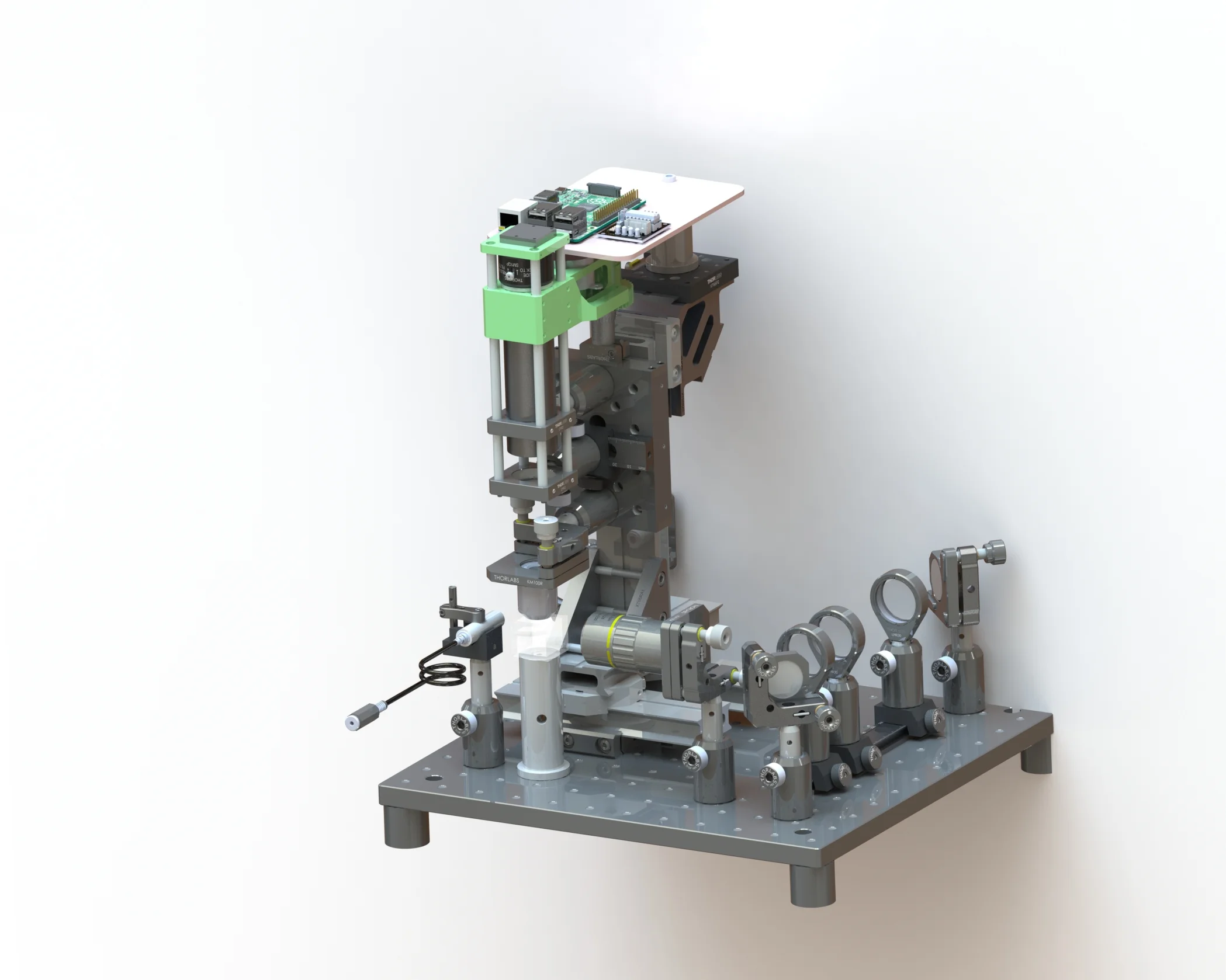
The overall optical geometry of the automated focusing light sheet system was based on well-established open source platforms in the field [1,2] however, a number of modifications were made to ensure proper alignment and operation of the autofocusing mechanism. Most critically, an upright geometry was adopted, as a means to maintain the orthogonal relationship between the illuminative objective and the detective image plane. A 405nm low-ultraviolet laser source is used, with a variable output power source. The laser power was measured after a collimating optical component, and configured for stable operation at 3mW total output. The laser then selectively passes through a NE10A neutral density filter with an optical density of 1.0, to reduce the power to 0.3mW during beam-tuning operations. To properly align the laser beam onto the optical elements of interest, two mirrors with a total of four degrees of freedom were utilized. A standard telescopic beam-expander of a 1:2 ratio were constructed of a 25mm and 50mm lens respectfully, as a means to increase the collimated beam diameter prior to the illumination objective. Logically, a larger numerical aperture on the back pupil plane of the illumination objective will generate a thinner Gaussian waist at that lens’ working distance, such a profile will more aptly approximate the condition in well-established commercial microscope systems [8-10]. A selective, 100mm cylindrical lens is employed, such that one may select between a discrete beam of light, or an illuminative sheet, as in more standard geometries. Positioned at the focal length of the cylindrical lens, is the illuminative objective from Mitutoyo. It is a PLAN-APO 10X / 0.28 NA; with a working distance of 34.5mm. Although this objective lens is designed primarily for machine-vision applications, it is ideally suited for light-sheet imaging due to its chromatic correction and exceptionally long distance working distance, from the surface of the lens to the point of focus.
To detect the fluorescent signal provided by the illuminative laser beam, a 5X / 0.05 NA lens from Edmund Optics is positioned orthogonally, 12.5mm from the illuminative axis. In order to maintain the 5X magnification relationship of the objective onto the camera, a standard 200mm achromatic “tube lens” was employed, as a means to generate an image onto the Sony IMX219 CMOS sensor. A 525nm +/- 25nm single band pass filter was positioned along this beam path, to spectrally select only fluorescent photons of interest, and restrict the effect of the illuminative laser on the image itself. This entire detective assembly is positioned on a mechanical, linear translation stage, ThorLabs PT1, which makes use of a Mitutoyo micrometer for fine positioning, with an accuracy of 630 um/revolution. A series of custom-designed components are used in order to support the camera and stepper motor, as well as reduce and translate the rotary motion of the motor to the manual micrometer stage. The entire detection assembly is built on a set of optical construction rails which enable three degrees of translatory freedom, in order to adequately position the components at the waist of the illuminative laser lightsheet.
In order to effectively detect the laser beam and assess the overall focus of the system, a specific sample was created. We use a 2cm cubic glass cuvette, with a wall thickness of 2.5mm, filled with a 1:1000 dilution of a GFP-fluorescent salt, which is photo-activated at 405nm. This results in an emission of longer wavelength light (approximately 510-520nm) taking the exact form of the laser’s profile. Using the emission filter, just before the image sensor, which blocks all wavelengths except those of the emitted fluorescence of interest, we can ensure that no reflection or scattering from the laser contaminates the image of the beam profile on the CMOS sensor.
Four critical hardware components were designed using SOLIDWORKS 2015-2016 to fit the specifications of our hardware system. They are outlined and described below:
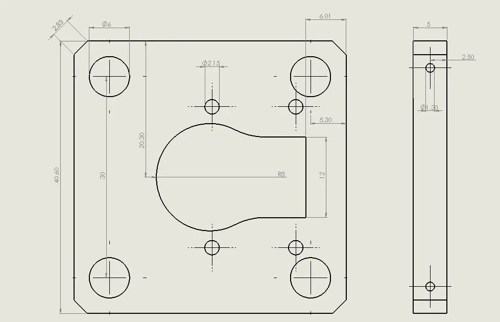
- PI Camera Support / Adapter Plate: The PI Camera must be positioned centered along the detective axis in order to achieve the highest possible resolution and performance from the optical system. Because the position of the image sensor relative to the electronic board of the camera itself is offset by a significant distance, an adapter plate had to be designed. Additionally, the adapter plate includes a specific configuration of 6mm through holes, to interface well with the ThorLabs 30mm cage system.
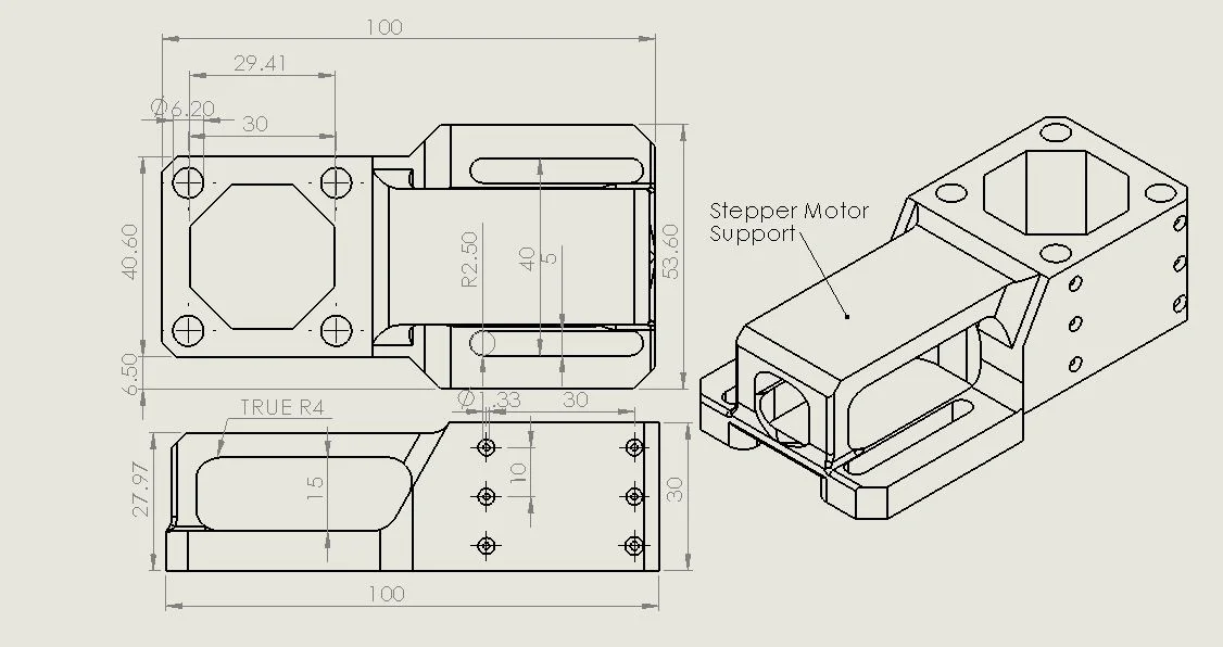
- Stepper Motor Support: One of the most critical elements in the robotic autofocusing system is the stepper motor itself, which actuates the linear stage and drives the position of the detection objective in depth. This component’s design requires some free degrees of freedom, in order to position the motor (and gear-train) in an optimal position. As such, a slotted motor support was designed, with the ability to fine position the distance of the stepper motor relative to the micrometer’s drive gear. Much like the camera support, this component was designed to interface with the ThorLabs 30mm construction cage system, to maximize strength and ease of assembly.
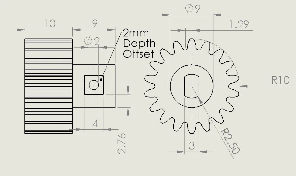
- Stepper Motor Pinion Gear: Fine positioning of the detection objective is of the most importance to the overall robotic system. In order to achieve this, a series of gears were designed to transfer rotary motion from a stepper motor to a manual linear stage. Because the system itself relies on small translations defined by a stepper motor, a 1:2 gear reduction system was developed, to reduce the rotary translation of a single step by a factor of two. The drive gear was designed in SOLIDWORKS with 16 teeth, and an external dimension of 15mm, in accordance with an online Excel gear design table provided by [11]. The interface with the stepper motor was measured and designed for our specific case, with a threaded hole for a grub-screw to ensure tight interfacing.
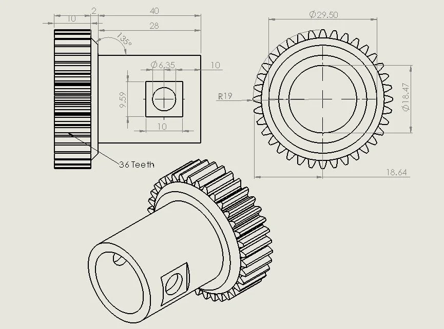
- Micrometer Drive Gear: In order to ensure high angular resolution from the stepper motor on the micrometer drive gear, it was designed to be twice the diameter, with twice the number of teeth (36). The parameters were altered using the Excel design table used to produce the previous stepper motor pinion gear [6]. Understanding the specifications of the stepper motor were critical in the design of the drive gear, since it ultimately defined the final single-step translation resolution of the robot system in depth.
Each component was 3D printed using a MakerBot Replicator 2, located in the Nano & Pico Characterization Laboratory in the California NanoSystems Institute. Printing parameters were defined using MakerWare v2.4.1, and everything was printed as follows: {Standard Resolution, 60% infill, Rafting ON, Support ON, Layer Resolution 0.2mm}. These parameters were selected following several days of failed prototype prints. Initially, several issues with incomplete component filling, lifting from the printbed, and non-uniform extrusion rates limited design progress. Additionally, each component required iterative redesign following post-printing evaluation. Some components weren’t able to be effectively printed as intended, due to limitations of the FDM process, or the fact that the dimensions and tolerances of the desired components were inconsistent with that of the original design. After systematic compensation and mitigation of these known errors both in redesign and post-printing machining, components were able to be integrated and tested in the final robotic system.